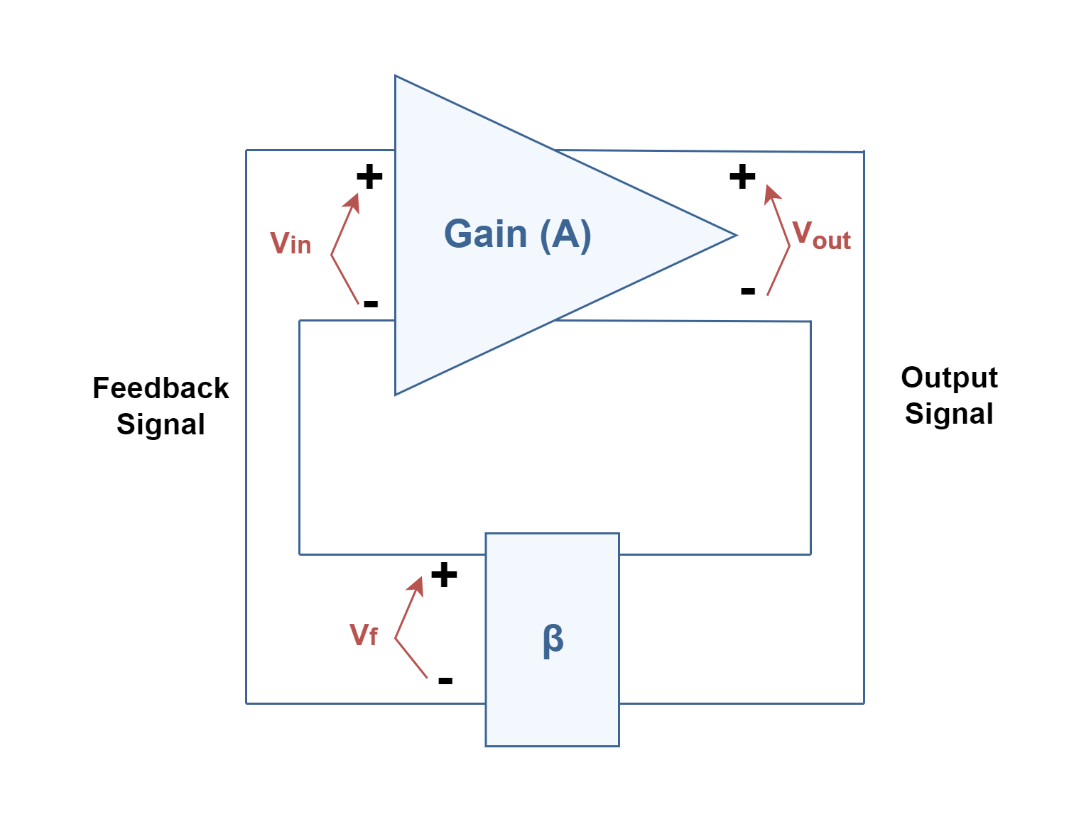
The Positive Feedback in Electronics Circuit Diagram the system gain with feedback is the ratio of the above actual output and input expressions, which reduces to Gain = A/(1 - Aβ) If we have a circuit that has its voltage gain reduced by 20 dB due to the application of feedback, then Gain is 1/10, giving Aβ, the feedback factor, a value of -9. Distortion Reduction
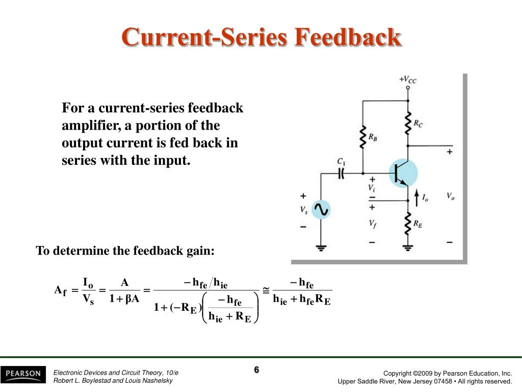
- Decompose fully differential circuit into common/diff. mode loops - If a local feedback loop can be modeled as a combination of a stable controlled source and passive impedances, the multi-loop circuit reduces to a single loop [Hurst 94]. - If there is a common breakpoint that breaks all feedback loops feedback will be less dependent on frequency variations. In some cases the resistive feedback removes all dependence on frequency variations. • If the feedback includes frequency dependent components (capacitors and inductors), then the frequency response of the amplifi i ffifier will be affected. Electronic Devices and Circuit Theory, 10/e 1. Feedback circuits (a) Feedback . The definition of feedback is a system which has portion of the output returned to its input and form as a part of the system excitation. The block diagram of a general feedback circuit is shown in Fig. 4.1. As Fig. 4.1 shows, the output signal is sampled and it is then sent to
What is Feedback in Electronics? Circuit Diagram
Engineers utilize negative feedback to ensure stable and linear operation, while positive feedback is harnessed for applications such as oscillators and switching circuits. Understanding the nuances of feedback and its effects on circuit behavior is critical for designing high-performance electronic systems. In electronics, feedback is defined as the process of returning part of the signal output from a circuit or device back to the input of that circuit or device. Feedback systems are widely used in amplifier circuits, oscillators, process control systems, and in many other areas. Benefits of a feedback system include the ability to precisely
The I/O impedances of the forward amplifier and the feedback network are far from ideal. Thus, the feedback network tends to "load" the amplifier at the output and also alter the input network significantly. The following issues need to be addressed: 1. To find the open-loop characteristics, we need to disable the feedback
PDF Chapter 14Chapter 14 Feedback and Oscillator Circuits Circuit Diagram
Feedback Circuit Techniques Lecturer: Kent Lundberg All electronic systems employ feedback. All analog circuits, including op amps, oscillators, filters, and power supplies (just to name a few), critically depend on feedback. Understanding feedback theory, and its use in practical applications, is the key to successful system design Feedback plays an important role in every system. Majority of practical electronics systems and circuits employ feedback. Feedback in electronic circuits can be of two types 1. Positive Feedback 2. Negative Feedback 1. Positive Feedback Here feedback voltage adds to the incoming input OR feedback voltage has same phase