How To Make Solar Panel in Charge Controller Wiring Diagram Circuit Diagram The fully charged level of your cells should be at around 4.1V or 4.2V. For this you will need a 9 V solar panel, with a 4.1V charge controller circuit. Restricting the controller output at 4.1V will ensure no cut-off is needed, and the charging can continue as long as the solar voltage is available.

ARDUINO PWM SOLAR CHARGE CONTROLLER ( V 2.02): If you are planning to install an off-grid solar system with a battery bank, you'll need a Solar Charge Controller. Short circuit and overload protection . In this new design, I used a 600-watt bidirectional TVS diode (P6KE36CA ) to suppress the lightning and overvoltage at the PV
Solar charge controller design resources Circuit Diagram
The MPPT Charge controller circuit that we design in this project will have the following specifications meat. It will charge a 2P2S battery (6.4-8.4V) Charge current will be 600mA; The complete Solar Charge Controller Circuit can be found in the image below. You can click on it for a full-page view to get better visibility. In this article, we are going to learn about the solar charge controller. There are different types of solar charge controllers in the market. All these have different working principles. But the basic principle is the same. In this article, we will learn the basic principle of the solar charge controller and a few details with a circuit diagram. Now let us design the MPPT Solar Charge Controller project using Arduino. A lot of calculations and complex algorithms is considered while designing this project. Schematic/Circuit Design. A solar panel will generate different voltages depending on different parameters like the quantity of sunlight, connected load & temperature of the solar

The next stage in your DIY solar charge controller project is to create the solar charger circuit. How the Solar Charger Circuit Works. To understand how to build the circuit, you first need to understand how it works. The circuit ensures that the batteries are charged from the solar panel and blocks any reverse current flow during the night

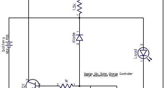
Basic Solar Charge Controller circuit Circuit Diagram
Our integrated circuits and reference designs help you create smarter and more efficient solar charge controllers, effectively converting power from a solar system with MPPT, safely charging various battery chemistry types and accurately controlling power flow. Design requirements. Solar charge controller designs often require:
